Roofline Closure Systems

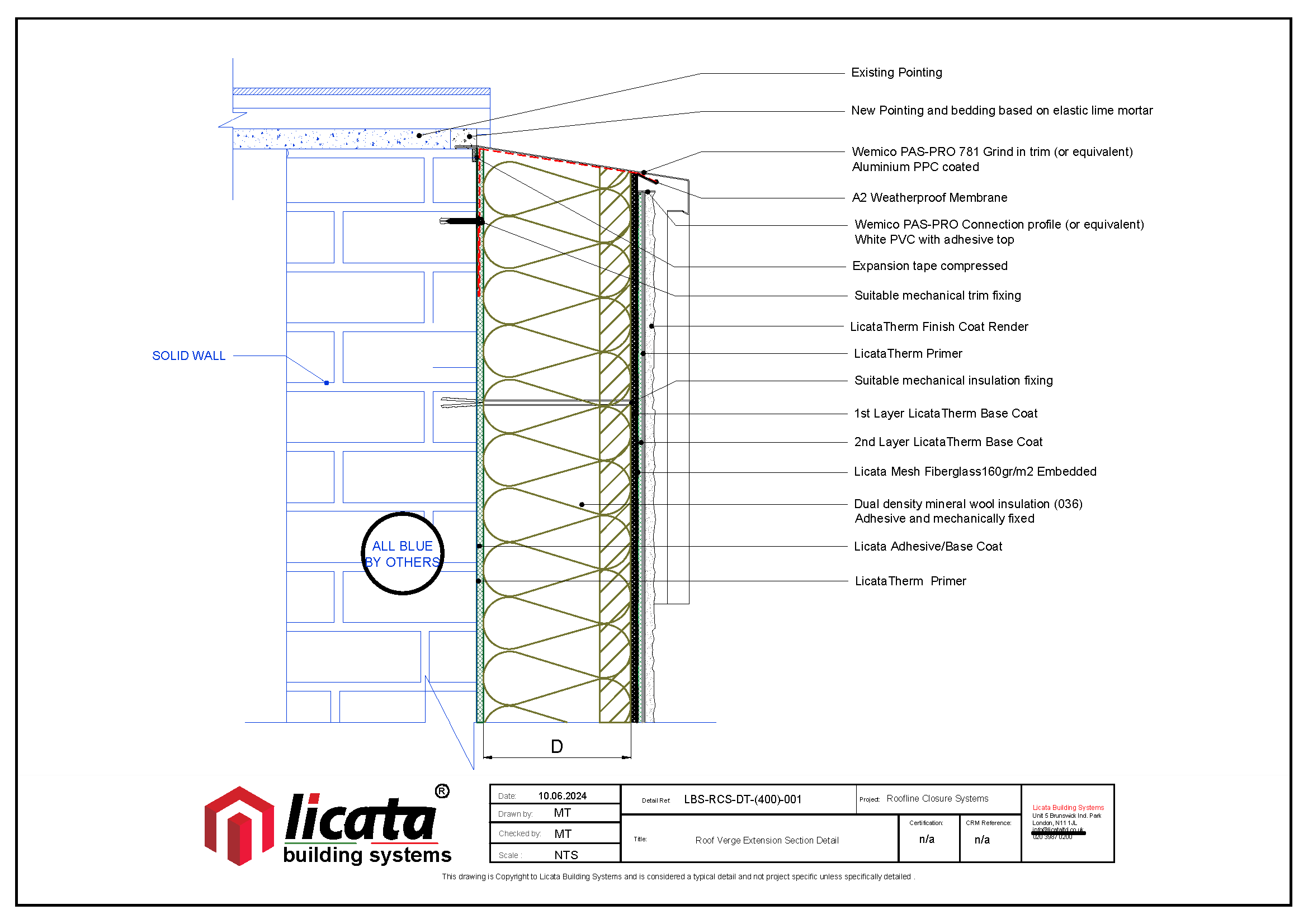
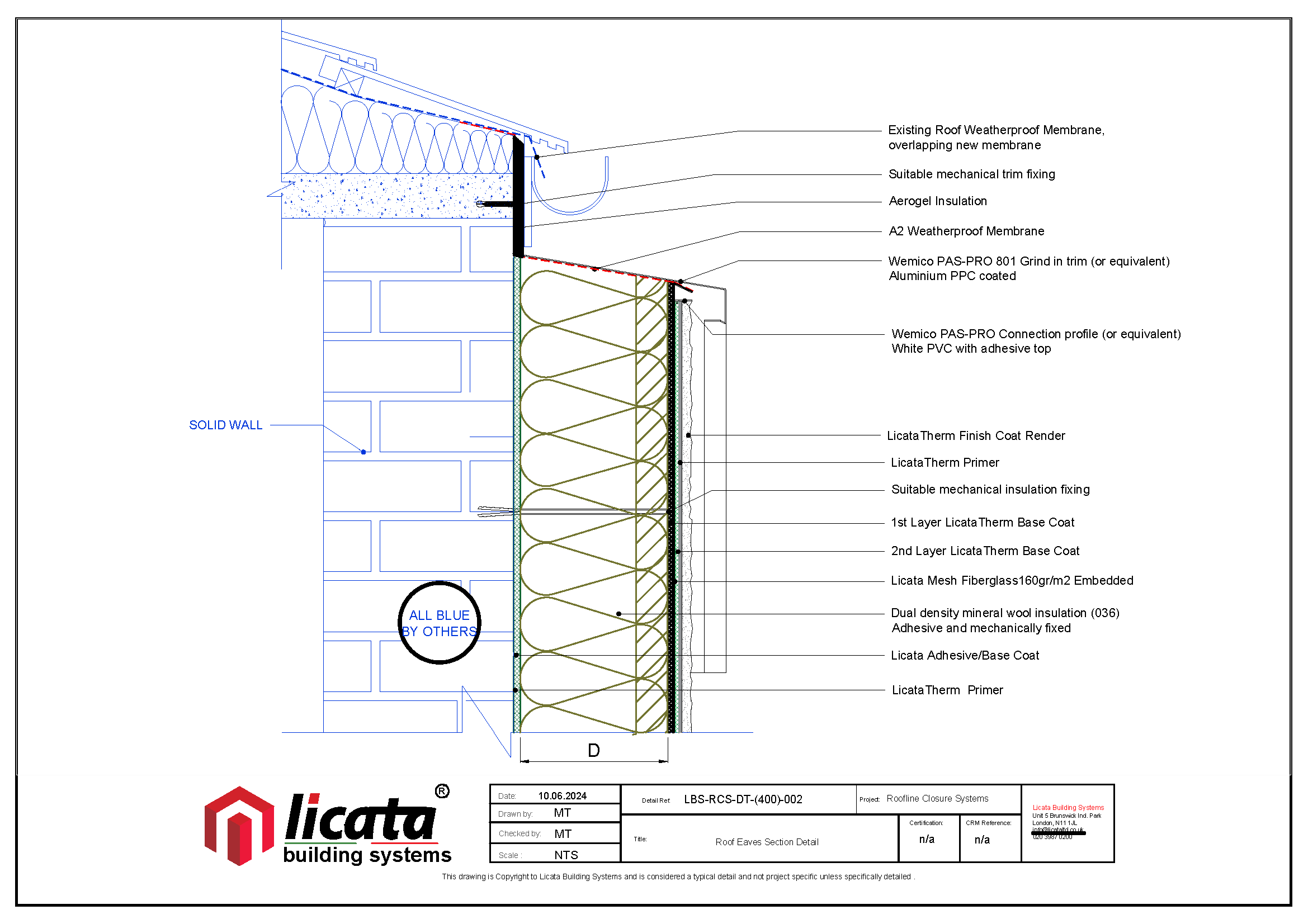
Roofline closure systems have now been approved for PAS projects, which means that metal flashings can be used to protect External Wall Insulation (EWI) systems instead of extending rooflines, although, extending the roofline is the most recommended option.

Because roofline needs can differ greatly depending on the specific project or property, a variety of solutions are necessary. Since standard design details can’t account for every situation, a set of Design Principles has been created. These principles offer flexibility while still ensuring that EWI systems are protected effectively and last for a long time.

Here’s a summary of the new guidance and what you need to know about installation going forward.

Step 1: Design Principles

Roofline closure system solutions are developed based on a set of core Design Principles. This ensures that the designs can be customized to fit the various rooflines and features of different properties, as long as these principles are followed. For further details, see the information below.

Design Principles

Redundancy of Seals

– Utilise at least two layers of weather protection.

– Avoid relying solely on sealants for waterproofing.

– Consider additional redundancy with trim or membrane.

– Double-seal all joints.

– Provide secondary waterproofing at eaves.

– Ensure appropriate system overhang per exposure zone

Gable-to-Eaves Junctions

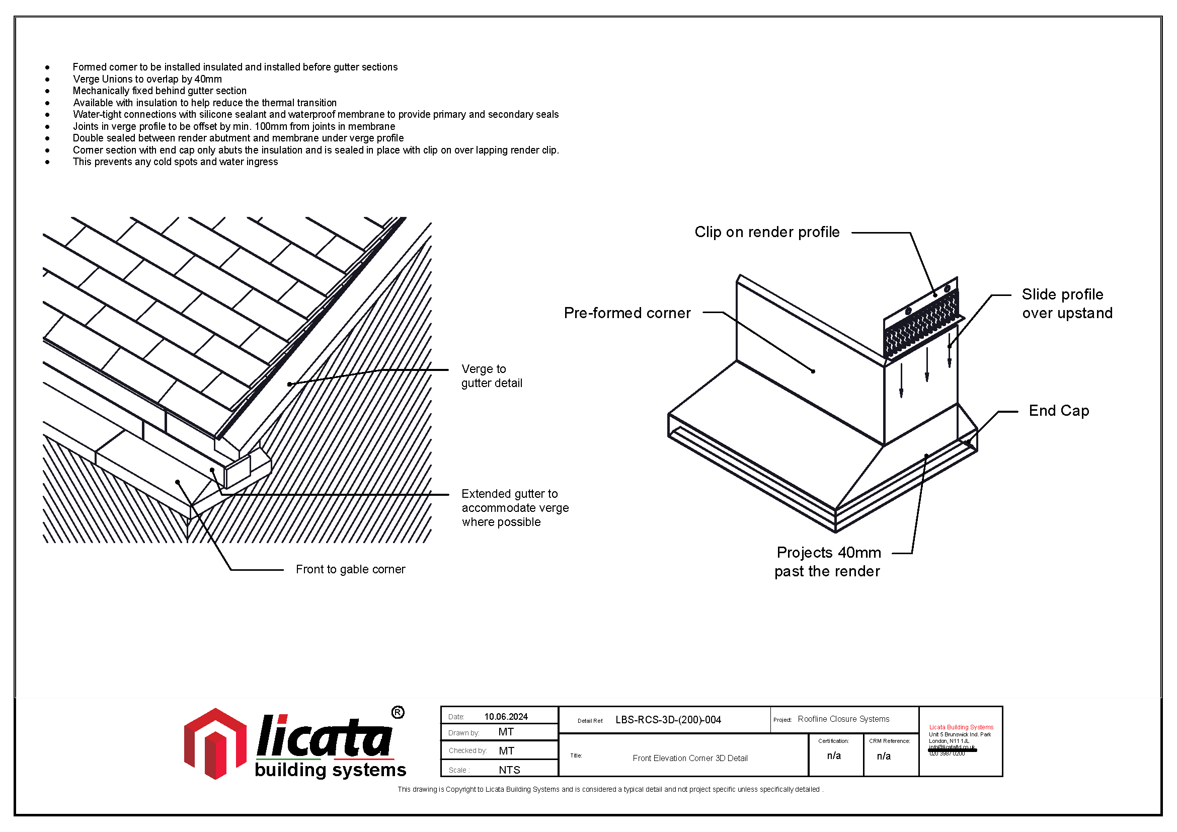
– Use overlapping, prefabricated units.

– Prohibit site fabrication except for minor trimming.

– Stagger joints by 100 mm.

Gable Apexes Formation

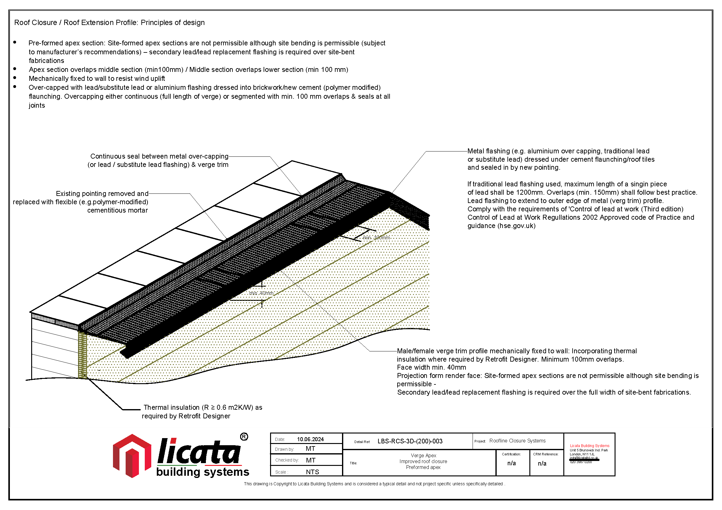
– Use prefabricated elements.

– Use site bent flashing with secondary lead flashing if necessary.

– Prohibit site-formed mitre joints.

Jointing Pieces/Connectors

– Use connectors with extended sides.

– Seal connectors to metal profiles.

– Stagger joints by 100 mm.

Soffit/Roof Overhangs

– Embed flashings/trims into masonry or below cement pointing.

– Overlap joints between redundancy layers by 100 mm.

– Replace sand and cement fillet with flexible mortar.

Thermal Bridging

– Ensure insulation continuity for minimum thermal resistance

Lead Flashings

– Limit single-piece lead length to 1200 mm.

– Follow best practice for overlaps and installation of lead or lead replacement flashings.

*Roofline Closure details that don’t meet the specified requirements cannot be used in any funded or private projects that require a third-party warranty.

Step 2: Survey Suitability

To successfully install Roofline Closure Systems, it’s important to conduct a comprehensive property survey first. This survey is crucial for determining if the systems are appropriate for the property and for identifying all the necessary details. Catching these details early is key, as they may involve various specific requirements.

Precise measurement and documentation of the current roof overhang are critical because they influence the specifications needed for the installation. Additionally, assessing the condition of the substrate is essential to ensure the property can support the installation, especially when grind-in flashings are involved.

2 Column Table with 8 Rows
Assessment Criteria
1. Relevant Details What will work with the existing roof line/substrate
2. Existing Overhang Ensuring it is consistent across the eaves/verge.
3. Rafter Positioning Rafters may need to be boxed in, worked around, or altered.
4. Substrate Condition Ensure the substrate is stable and will not be damaged by grinding in, especially where grinding in is to be considered.
5. Existing Insulation & Potential Cold Bridging Ensure continuity of roof insulation and a minimum thermal resistance of 0.6m²K/W when installing each detail.
6. Corner Details Confirm how the eaves and verge will meet and identify the best detail, including which corner profile is suitable if required.
7. Existing Features Consider features like corbels and quoins, which may prevent the installation of these details, potentially requiring site-specific designs.
8. Ventilation Ensure roof ventilation is not obstructed or restricted when installing Roofline Closure Systems.

*Some properties have roof junctions that are so challenging to address that extending the roofline may be the best solution.

Step 3: Second Line of Protection

The Roofline Closure System Principles mandate two layers of protection over the top of the EWI system. This can be accomplished in different ways, with Licata providing two standard options. The choice of installation method will determine the specific Licata details needed.

Membrane VS Secondary Flashing

Membranes

Adding a membrane beneath the primary flashing can be a cost-effective approach. Licata offers a specialised membrane stop bead (MSB) designed to be placed at the top of the insulation board, featuring an adhesive tape to secure the front of the membrane.

Secondary Flashing

Adding a secondary flashing beneath the existing one can be a quick and straightforward solution. This approach is often more practical, particularly when dealing with installation in challenging UK wind and weather conditions. The Licata TCP Under Trim is an angled flashing that easily fits below the primary flashing to provide the necessary protection. The trims interlock and overlap, eliminating the need for jointing pieces.

Step 4: Guide Information

The Licata Roofline Closure System Guide outlines different solutions, with the best option depending on factors like the existing overhang, the chosen secondary protection, potential cold bridging, and the specific characteristics of the property’s current roofline.

Step 5: Installation Checklist

When installing the Roofline Closure System, you need to fill out a checklist that details how the installation aligns with the system’s principles. Additionally, you must take photos of the different stages of the installation process. Both the completed checklist and the photos are necessary when applying for a project warranty.

Step 6: Minimum Material Specification

The principles of the Roofline Closure System set out minimum standards for the flashings that Licata components are made to meet.

Minimum Material Specification
Suitable Base Material – Minimum Aluminium specifications 1050A. Minimum Stainless-Steel specifications 304.
Minimum Thickness – 1.2 mm aluminium with a tolerance of +/- 10% to be used for trim widths up to 160 mm. For trim widths over 160 mm or trims to be used in exposed areas, (minimum 50 mm overhang) 1.5 mm aluminium must be considered for added strength and stability.
Coating Requirement – Polyester Powder coated aluminium must have a minimum coating thickness of 40 microns to BS or Qualicoat standards and Powder Coaters must be BS or Qualicoat-approved applicators. Pre-coated aluminium must be polyester coated on both sides and the thickness must conform to EN 13523-1.

Contact Our Technical Team

If you have any questions, need more details, or want to talk about your specific project requirements, feel free to contact us. Our team of experts is here to listen, collaborate, and offer customised solutions.